

ROTARY DIE CUTTING · CONTINUOUS CONVERTING
Rotary die cutting: die-cut parts on rolls
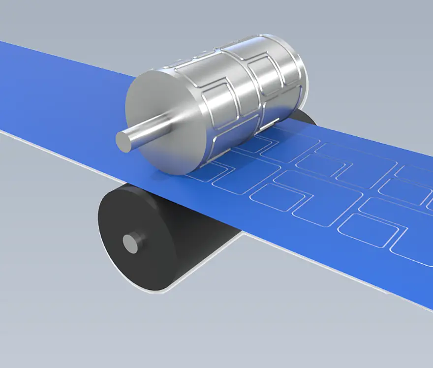
Rotary die cutting continuously shapes suitable roll-fed materials into the required contours. We align the material, die-cut pattern and delivery format with your downstream process.
400 mm
Max. material width in cleanroom
01
ROTARY DIE CUTTING OF ROLL MATERIAL
Cutting contours continuously from a material web
Rotary die cutting is a continuous manufacturing process: suitable, windable material passes through rotating dies. The required contour is repeated along the web. The parts can be supplied on a roll for subsequent removal or application.
To design the process, we consider the material, layer structure, geometry and downstream handling together. For self-adhesive constructions, the carrier or liner also matters: selected layers can be cut while a backing remains as the transport carrier. Waste matrix removal and any application aids are specified for the intended handling.
Tell us about your material so we can assess whether it can be rotary die cut at a thickness of up to 2 mm. We agree the achievable tolerances for your contour and application.
02
FROM MATERIAL TO DIE-CUT ROLL
Step 01
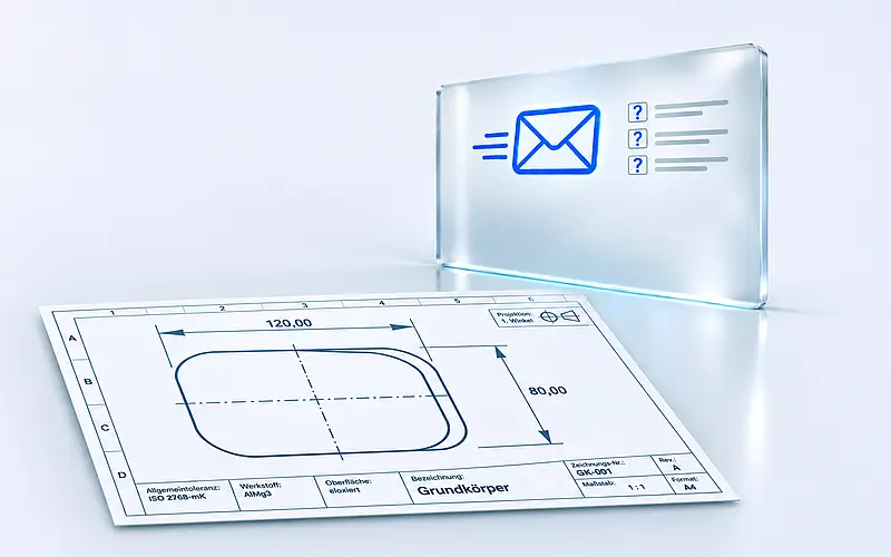
Discuss the requirement
Tell us the application, input material, contour and desired delivery format. A drawing or sample helps with the assessment.

Step 02
Assess material and geometry
We assess windability, layer structure and contour before selecting the appropriate die-cutting method.

Step 03
Agree on the design
We clarify the carrier, part layout and application aids. A sampling phase can be agreed if required.
Step 04
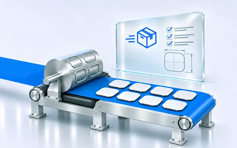
Produce the die-cut parts
Once the design is agreed, we produce the parts and prepare the agreed delivery format for your downstream process.
03
ROTARY AND REGISTER-CONTROLLED CUTTING
Continuous rotary die cutting
A rotating die continuously cuts contours into suitable roll materials. Suitability and design depend on the material and contour. Die cutting adhesive tape →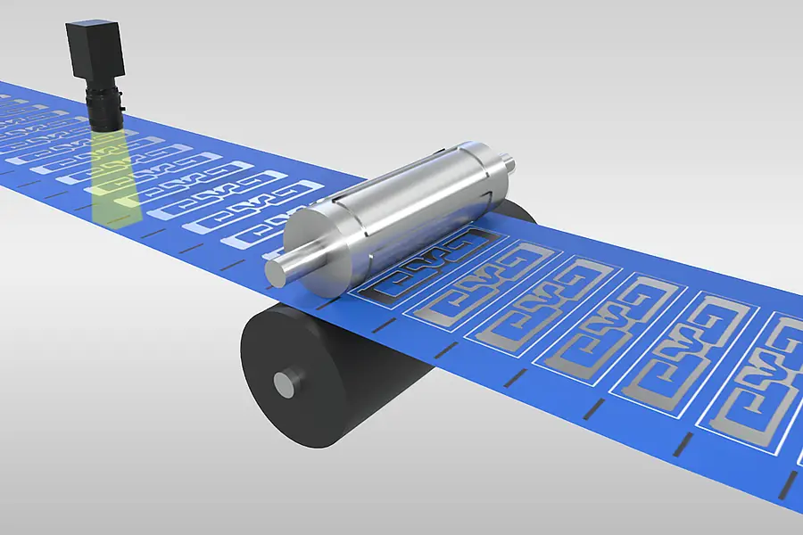
Servo rotary die cutting
Camera-assisted position detection helps place cuts at defined points on the web. It is an option to assess for register-related requirements. View die-cutting methods →04
DIE-CUT PARTS FOR FURTHER PROCESSING
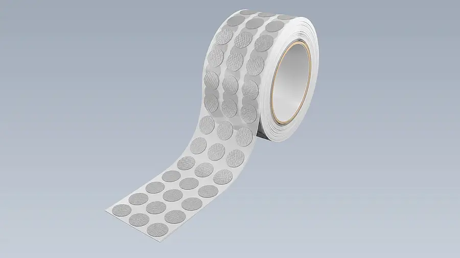
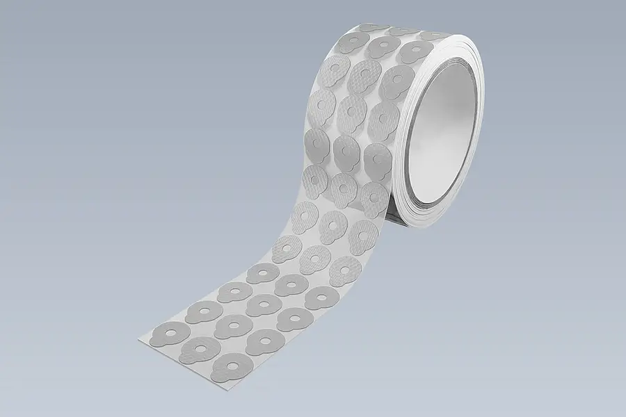
Die-cut parts on a roll
Repeated contours remain arranged on a continuous carrier web for removal or application. Die cutting adhesive tape →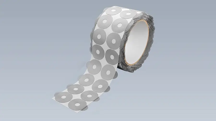
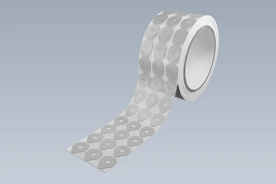
Parts with a lifting tab
An agreed lifting tab can help remove and position a self-adhesive die-cut part.05
WINDABLE INPUT MATERIALS
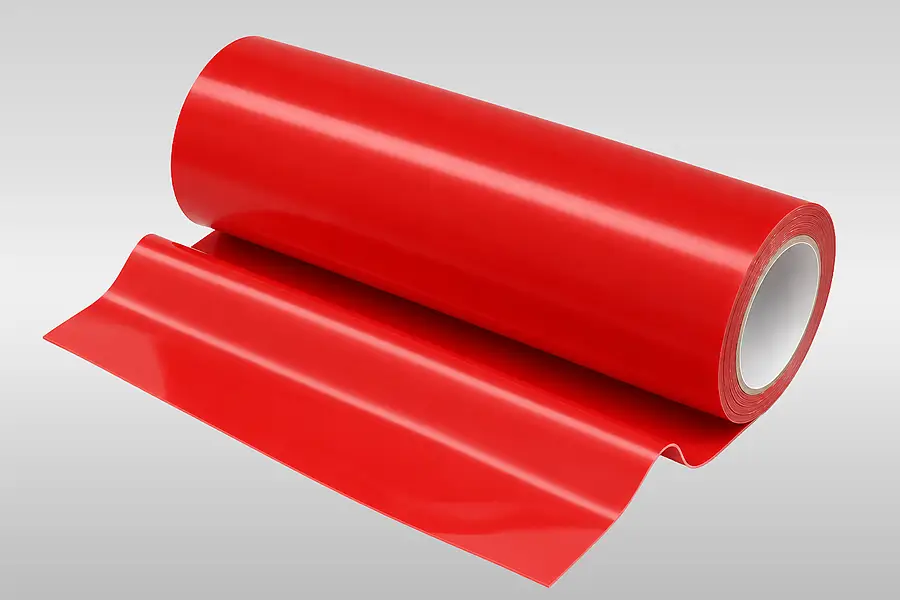
Adhesive tapes
Single- and double-sided adhesive tapes can be considered as windable input materials. Layer structure and liner handling shape the process. Die cutting adhesive tape →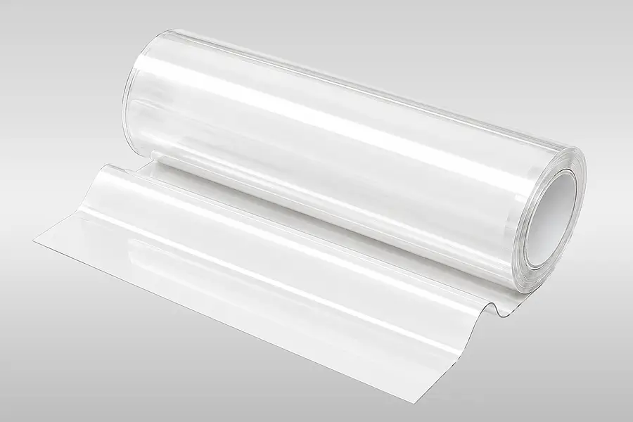
Technical films
Suitable technical films can be fed as a web and cut into contours. Material suitability is checked for each request. Die cutting films →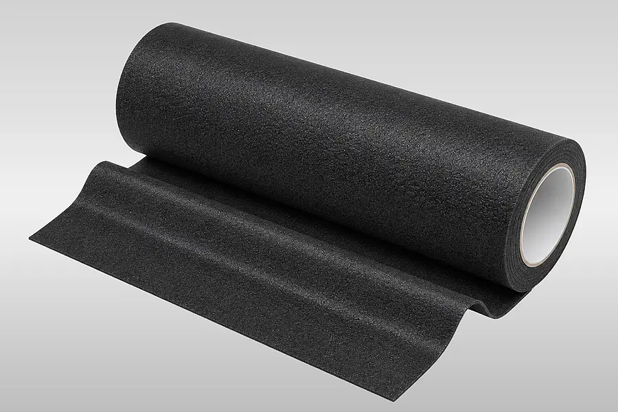
Foams
Windable foams can be rotary die-cut if their thickness, elasticity and contour suit the process. Die cutting foam →06
ROTARY DIE CUTTING IN THE PROCESS VIDEO
07
WHEN DOES ROTARY DIE CUTTING FIT?
| Selection criterion | What it means for rotary die cutting |
|---|---|
| Input material | Suitable, windable roll material; assess material and layer structure case by case. |
| Material thickness | Existing guideline up to 2 mm, depending on the material. |
| Contour and position | Geometry and required position along the web determine the method. |
| Delivery format | Die-cut parts on a roll with agreed carrier and part layout. |
Material and contour matter
08
DETAILS FOR YOUR DIE-CUTTING ENQUIRY
Tell us about the application and the required outcome. Useful details include the input material and layer structure, a drawing of the contour with dimensions, the required quantity and the delivery format. Please also describe whether the parts should remain on a carrier, be removed manually or be applied by an automated process.
If you have material samples, winding-direction details or positioning requirements, please include them. We can then assess the appropriate die-cutting method and agree on samples and inspection features if needed.
09
MORE ABOUT CONVERTING
10
ROTARY DIE-CUTTING QUESTIONS
When is register-controlled die cutting useful?
Servo rotary die cutting may suit a contour that must be positioned at a defined point on the material web. Camera-assisted position detection helps align the cut with the web. We assess whether this approach suits your input material and cutting pattern for the specific request.
What role does the liner play in rotary die cutting?
In self-adhesive constructions, the liner can carry the die-cut parts through processing. Which layers are cut and which backing remains depends on the construction and the intended method of removal. Include liner details and downstream handling in your enquiry.
Can die-cut parts on rolls have lifting tabs?
A lifting tab is a possible application aid when it suits the geometry and handling process. It can help grip and remove a die-cut part; its position and construction are agreed for the application. The illustration shows one possible design and is not a blanket promise for every material.
How are tolerances set for rotary die-cut parts?
Required tolerances are agreed for the specific material, contour and application. A general tolerance for rotary die cutting would not be reliable without those details. Tell us the critical dimensions and inspection features so that we can assess feasibility.
Enquire about die-cut parts on rolls
Send us your drawing, input material and intended downstream process. We will assess whether rotary die cutting suits the required design.

ROTARY DIE-CUTTING ADVICE
Thomas Klein
Contact for converting
Thomas Klein can discuss the input material, contour and suitable delivery format for your die-cutting enquiry.