

Die cutting
Plan contours, layer separation and delivery format to suit the application
Die cutting turns suitable base materials into shaped parts. Krückemeyer GmbH aligns the contour, material and delivery format with your component and subsequent processing step.
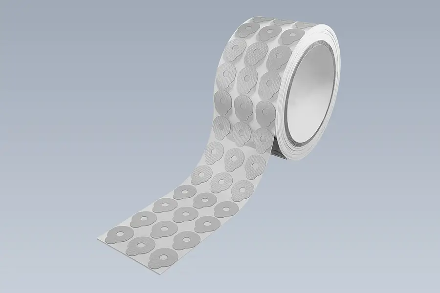
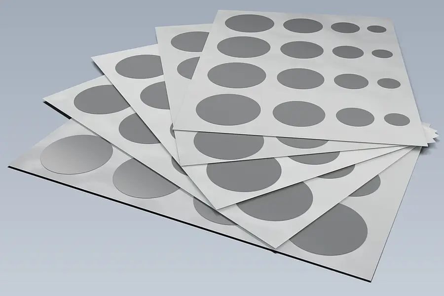
Consider shape and handling together — Die-cut parts can be supplied on rolls, on sheets or as individual parts.
01
In figures
up to 580 x 580 mm
Flatbed die-cut part size, depending on material
up to 10 mm
Foam thickness in flatbed die cutting
02
Die cutting and die-cut parts
How die cutting shapes base materials
Die cutting gives suitable base material a defined two-dimensional contour. The result can be a die-cut part made from adhesive tape, technical film, foam, rubber or coated abrasives. The material properties come from the selected base material; die cutting determines the shape. The adhesive tape die cutting detail page explains the design of adhesive tape die-cut parts in more depth.
Design decisions include the outer contour, possible internal cut-outs and the layers to be separated. With multilayer constructions, it is also necessary to establish whether the part remains on a carrier or is cut through completely.
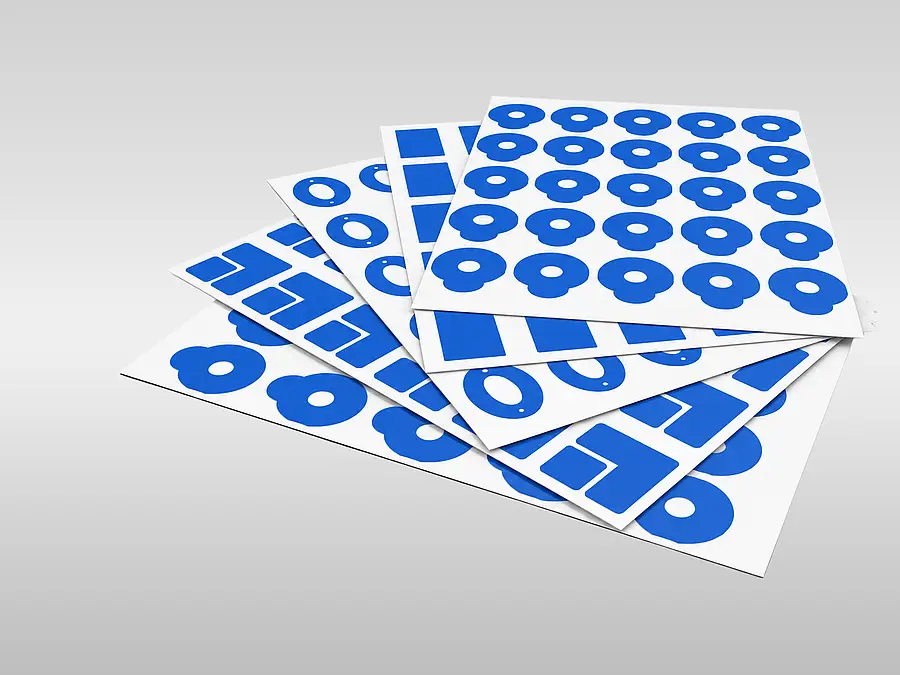
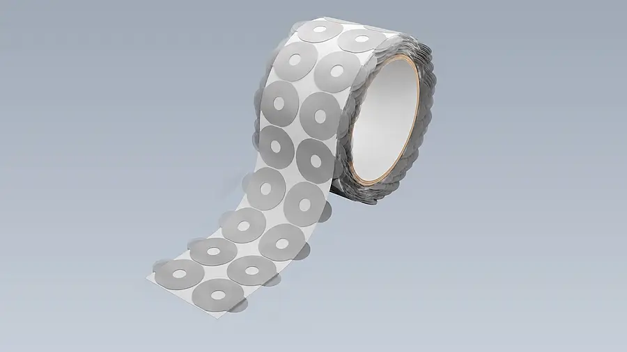
The delivery format follows the workflow: die-cut parts on rolls, on sheets or as individual parts place different demands on removal, positioning and application. Finger lifts and other handling aids can support these steps.
Base material, process and delivery format
These decisions belong together. Krückemeyer assesses material, geometry, dimensions and application before selecting the die-cutting process and format.
Die-cutting processes and materials
03
Die-cutting processes
How the shape is cut into the material
The process and layer separation depend on the contour, base material and required format.
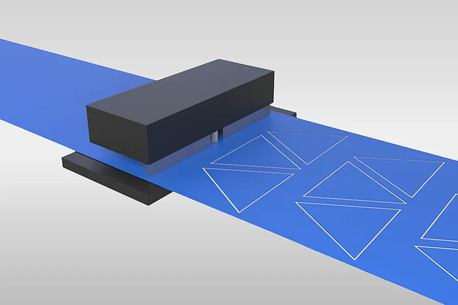
Stroke die cutting for shaped parts
In flatbed die cutting, a single stroke cuts the contour into suitable material. Internal cut-outs and the later delivery format are considered during design. Explore stroke die cutting →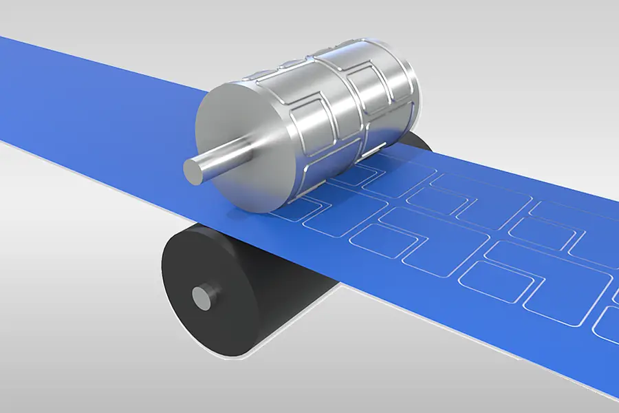
Rotary die cutting on a material web
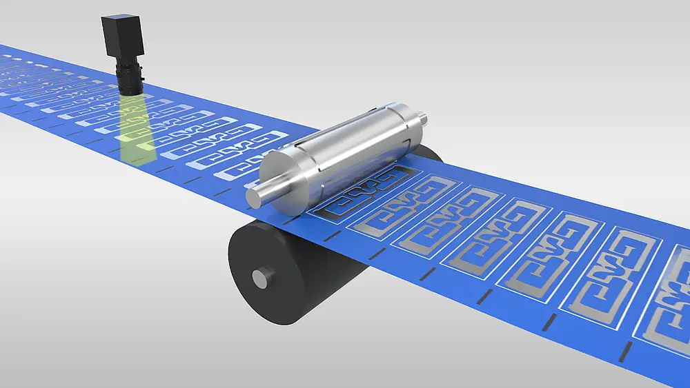
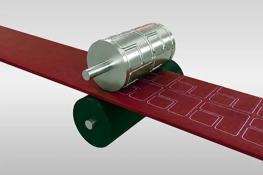
A rotating die processes material on a moving web. Material thickness and contour are matched to the process for the specific order. Explore rotary die cutting →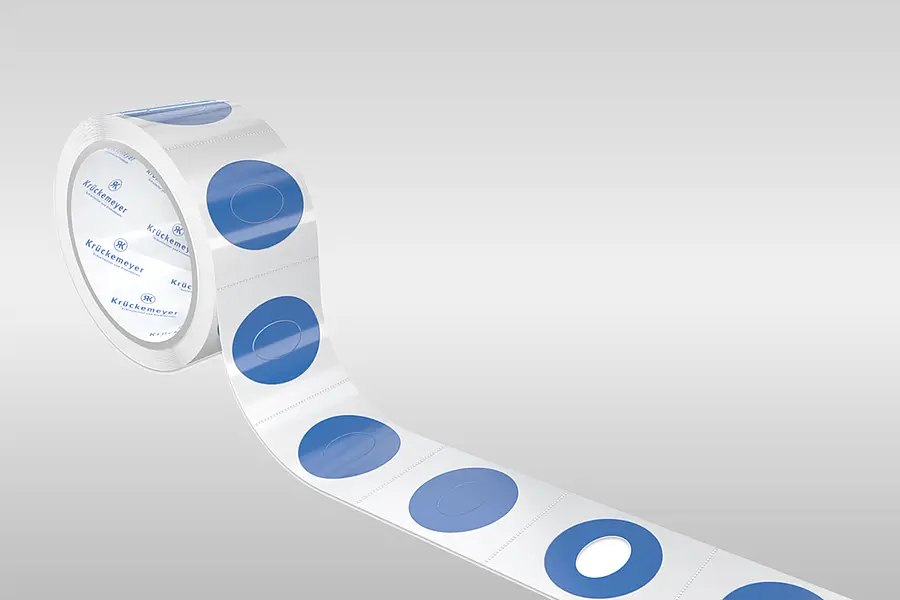
Kiss cutting for selective layer separation
In kiss cutting, the specified layers of a construction are separated. The layers involved, including any liner, are defined according to how the parts are to be removed. Explore kiss cutting →04
Die-cutting selection criteria
Which details determine the die-cutting process?
The suitable solution depends on the task, contour, layer separation and handling.
Start with the required result in the application and a drawing of the outer and inner contours. Material, material combinations, dimensions and possible narrow webs influence feasibility. Flatbed die-cut parts have a material-dependent size range; its limits cannot necessarily be combined.
For multilayer materials, define the intended separation: kiss cutting selectively separates layers, whereas full die cutting separates the specified layers completely. Whether a carrier remains in place is part of the specific design.
Plan subsequent removal and application as well. Rolls, sheets and individual parts are different delivery formats; finger lifts, pull tabs and positioning aids can support processing. Suitability is assessed for the material, geometry and application.
05
Technical data
Stroke/flatbed, rotary and servo rotary die cutting
The values depend on the material and do not constitute a general guarantee for every geometry.
| Process or characteristic | Specified range | Assessment |
|---|---|---|
| Stroke/flatbed die cutting: die-cut part size | from approx. 3 x 3 mm up to a maximum of 580 x 580 mm | Guide value for sheet or roll material; depends on material. The minimum size is not guaranteed. |
| Stroke/flatbed die cutting: web width and internal radius | approx. 2 mm | Guide value; depends on material. |
| Stroke/flatbed die cutting: foam thickness | up to 10 mm | Specified range value; depends on material. |
| Rotary die cutting: material thickness | 2 mm | Specified range value; depends on material. |
| Waste matrix bridge width | approx. 2 mm | Guide value, not a universal minimum requirement. |
| Servo rotary die cutting | Material, geometry, dimensions and design | Process variant; specific feasibility is assessed for each order. |
| Die cutting in an ISO 9 cleanroom | 400 mm material width; 390 mm die-cut part width; 550 mm die-cut part length | Maximum values in the cleanroom; assess the design for each case |
06
Die cutting by material and process
Find the right die-cutting task
The available detail pages lead from the base material or process to a specific enquiry.
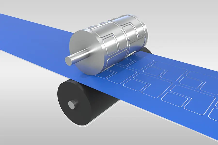
Adhesive tape die cutting
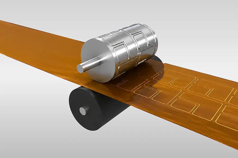
Film die cutting
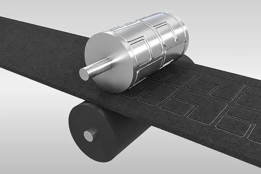
Foam die cutting
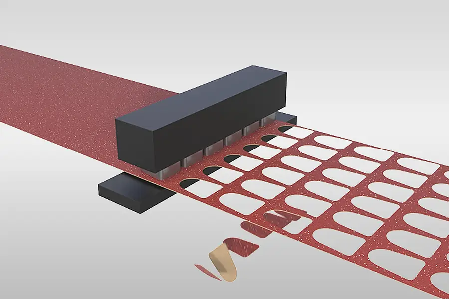
Coated abrasive die cutting
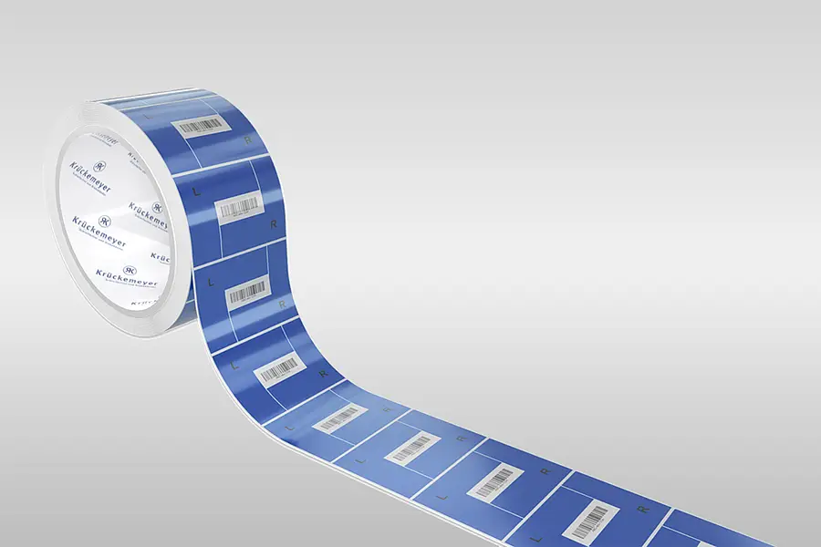
Label die cutting
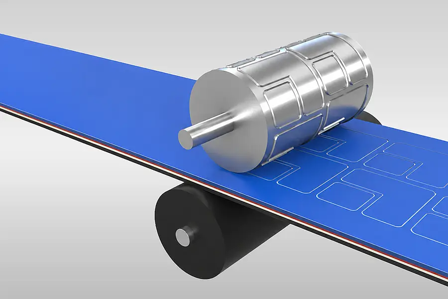
Laminating film die cutting
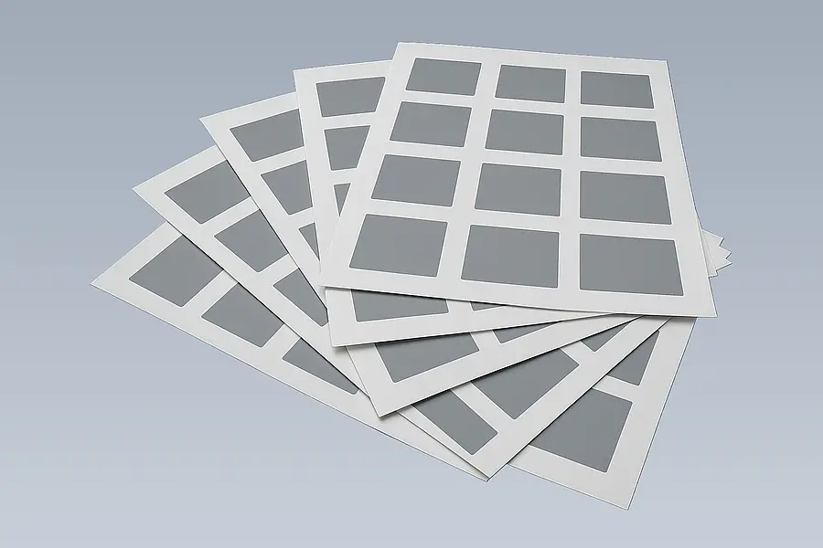
Stroke die cutting
Rotary die cutting
Kiss cutting
Rubber die cutting
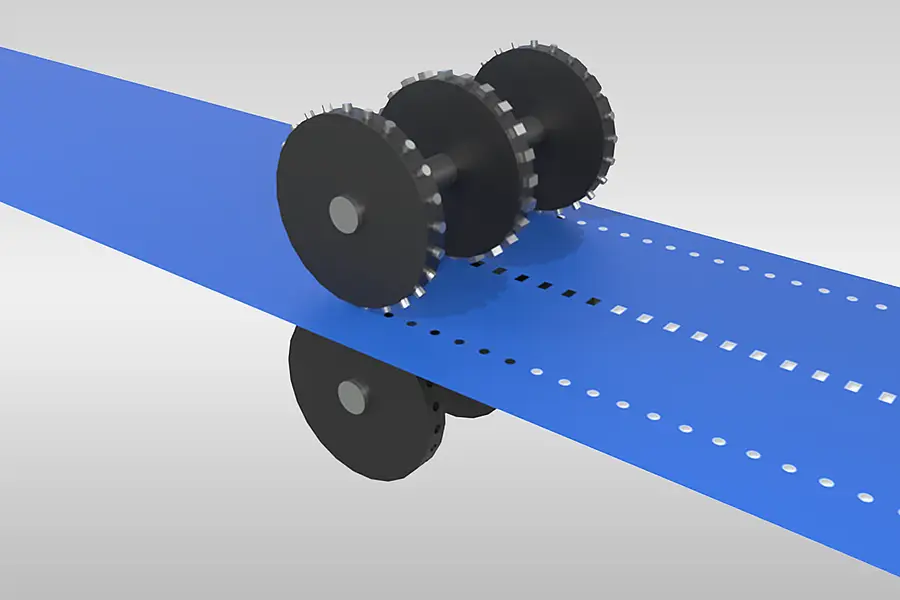
Perforating and punching
Choose the starting point that matches your task: the base material, a required layer separation or the manufacturing process. The detail pages explore each task further. Several steps can be combined when the base material needs preparation, a contour needs to be produced and a particular delivery format is required.
Die-cut parts on rolls or sheets
The arrangement of the parts, their spacing and how they are removed are aligned with the subsequent application process.
Shaped parts from coated abrasives
Coated abrasives can also be die cut. The finished abrasive tool and the base material need to be considered separately.
07
Die cutting in converting
From base material to an application-specific format
Die cutting can be one step in a coordinated sequence of preparation, shaping and delivery.
Krückemeyer can prepare or laminate materials, then produce the required dimensions and contours and define a suitable delivery format. The sequence depends on the material construction, geometry and application; it is not a fixed scheme.
For an enquiry, details of the application, required result, drawing, base material and processing are helpful. These provide a basis for agreeing on the process and possible aids such as finger lifts or positioning aids.
Application before process
The required contour alone does not determine the manufacturing process. Krückemeyer assesses the combination of material, dimensions, layer separation and subsequent handling.
- Assess the base material and material combination for the task
- Align the contour and layer separation with a suitable die-cutting process
- Design die-cut parts for delivery on rolls, on sheets or as individual parts
- Assess handling aids for removal and positioning
08
Frequently asked questions about die-cut parts
Answers on planning and production
Further questions about enquiries, cleanroom production and inspection of die-cut parts.
What information helps with an enquiry about die-cut parts?
A drawing and details of the application, base material and required design help with the assessment. Also explain how the die-cut part will later be removed and applied. If a product is already in use, its technical details and your experience with it are helpful. Krückemeyer uses this information to clarify the material, geometry, manufacturing process and possible handling aids. Exact feasibility is assessed for each case.
Can die-cut parts be produced under controlled cleanroom conditions?
Yes, die cutting is among the possible processes in an ISO 9 cleanroom. The specified maximum material width there is 400 mm; die-cut parts are described with widths up to 390 mm and lengths up to 550 mm. The combination of material, dimensions and design that is possible is assessed for each order. The cleanroom air classification is not a general statement about the particle cleanliness of the finished die-cut part.
When are the contours and dimensions of die-cut parts inspected?
Contours and dimensions can be inspected with optical measurement technology by customer-specific agreement. Measurable features include outer and inner dimensions, distances between holes or edges, and shape deviations. The inspection plan, sample size and permissible deviations are defined for the specific order. A particular measurement or general tolerance value is not automatically included for every die-cut part.
How does an idea for a die-cut part become a series design?
First, the application, material, geometry and requirements are clarified. Advice, a quotation and, if needed, trial production follow. The customer tests and approves a prototype in the application; changes are documented. The subsequent series design is agreed on this basis. This process allows the shape and handling to be assessed before they are fixed for ongoing production.
09
Next step for adhesive tape die-cut parts
Plan adhesive tape die cutting in more detail
The detail page shows which information matters for die-cut parts made from adhesive tape and their delivery format.
Enquire about a die-cut part for your application
Describe the base material, contour and processing. Krückemeyer will assess a suitable die-cutting process and format with you.

Advice on die-cut parts
Thomas Klein
Contact for converting
Discuss the material, geometry and delivery format for your die-cut part with Thomas Klein.